


I decided to check the bump steer on this chassis. Ultimately, this is very, very important and means a lot when cornering. All of the aftermarket people try to eliminate bump steer to get your car to handle.
Dale Schwartz pointed out that I have an early chassis and improvements have been made in later models. That being said, I currently don't have any initial set-up information for this chassis, but there are a couple of initial problems.
-The lower control arm and tie rod angles don't seem to be the same. The tie rod is on much more of an angle and the rack position isn't adjustable.
-The upper control arm was severely bound up. This required removing about 1/8" from one of the spacer/reducers which go into the upper control arm heim ends. The previous owner had to pound the heck out of the control arm to install it, and then it wouldn't move like it should.
-That being said, even with the heims screwed into the control arm as far as they would go, there is about 3 degrees of positive camber, when you want about 3 to 5 degrees of negative camber. The upper control arm needs to be shortened, but it isn't as easy as chopping about 1/2" from it. There is a cross bar in the way, so that also needs to move, but may interfere with the shock.
So, before any bump has been checked, modifications are required to the spacers and upper control arms.
Doing the bump...
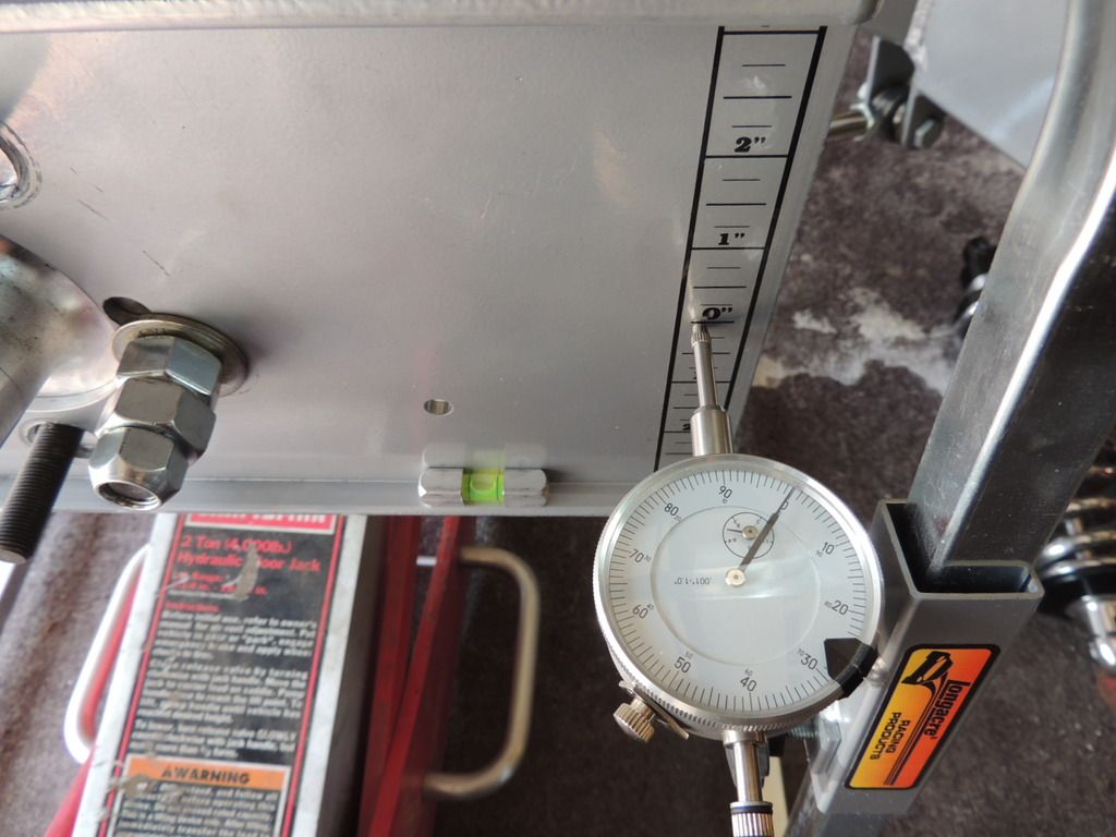
I initially centered the rack, set the lower control arm parallel to the cross member and leveled the lower control arm. I also set the toe to zero with the bump steer plate.
Bump at 1" thru 3"
1"
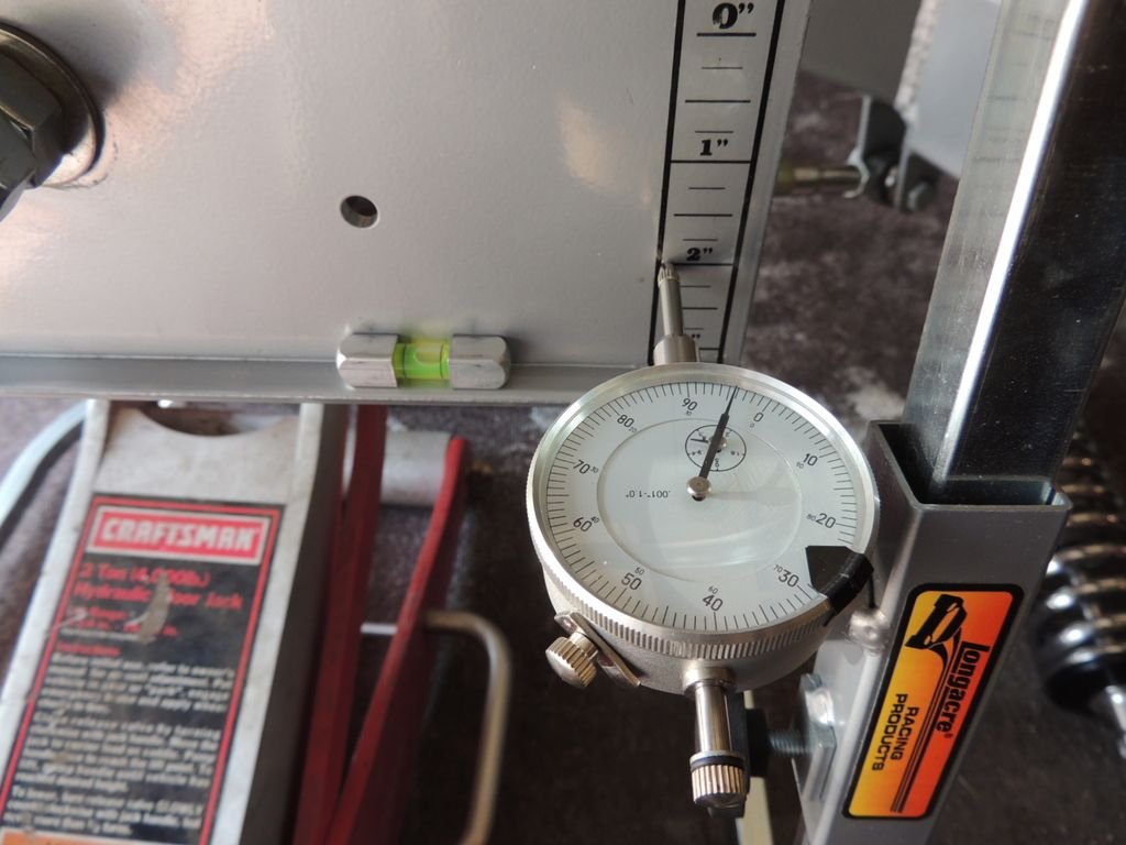
2"
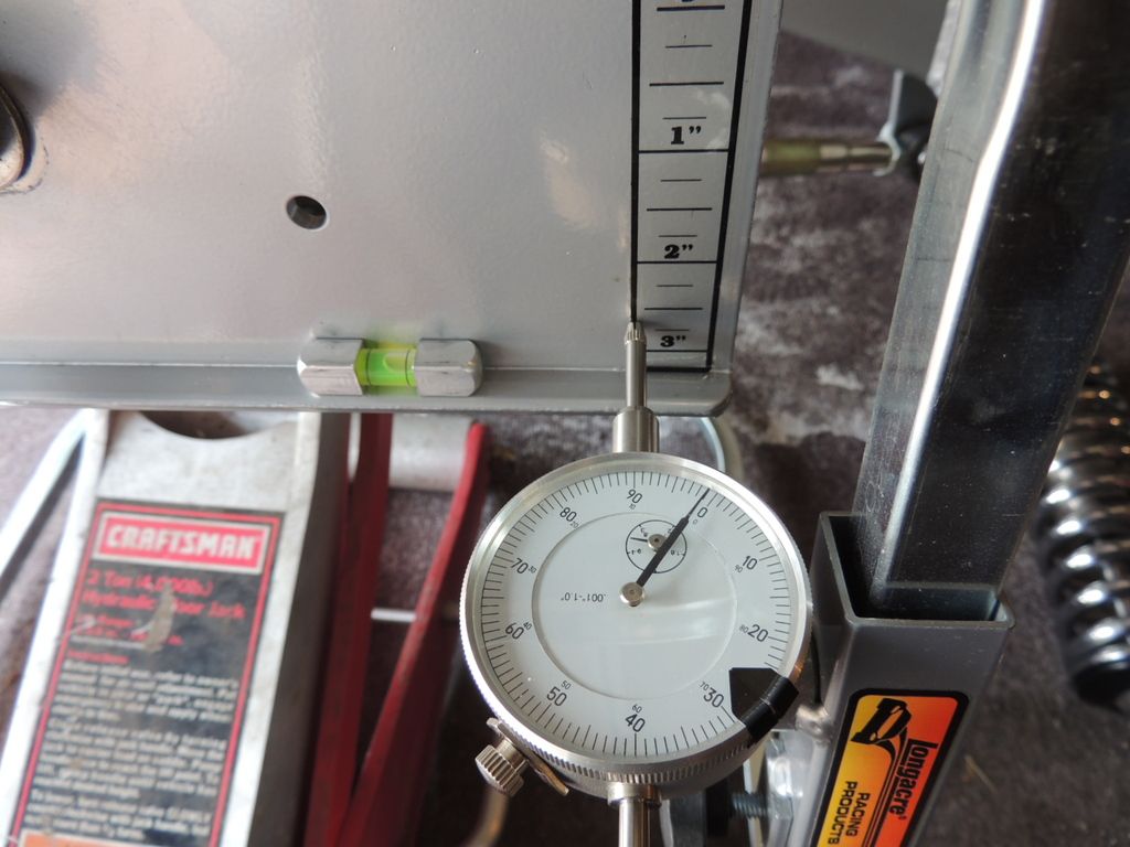
3"
Bump at 1" Droop
And back at Zero - Only .002 different from start, so repeatability was good.
All was toe in
1" was.057
2" was .109
3" was .170
Droop at 1" was .040.
Normally, when it is a consistent toe in, you lengthen the tie rod. So, I literally moved the lower control arm and tie rod end out 5/8", which was at the end of the threads on the rack. This made everything worse, much worse.
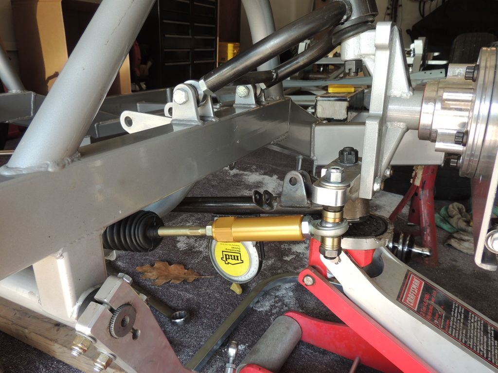
So, I moved the tie rod down with spacers, just to see what will happen. This brought the tie rod and control arm angles a little closer together and helped the bump quite a bit, but I need a bit more.
I moved it down about 7/16" which was as far as I could and still get a nut on it. Since this has a conventional OEM tapered rod end, then only thing I can do to fix it is make a new steering arm, or drill the arm and use a female heim on it with spacers. The arm actually looks as if it was built upside down. There is about 1/2" of material machined from the bottom of the steering arm with spacers as shown in this last picture. If the arm was the other way, then I think the bump would be a lot closer. It can't really be fixed because of the ball joint and tie rod tapers
This is not very good for a competition car. It was nearly 3/16" at 3" of travel. Normally a car with stock type spindles, this should be no more than .020 and aftermarket racing spindles, this would be less than .010.
Once again, the camber wasn't set which affects everything, but not a whole lot. It seems I have quite a bit of work to do as this was just the drivers side and I am sure the passenger side is about the same.
grr


 Reply With Quote


Bookmarks